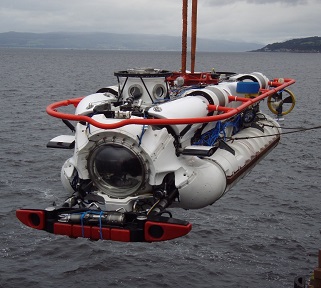
In the aftermath of a serious underwater accident, crew members onboard a distressed submarine can often be exposed to elevated pressures for significant periods of time before rescue can be arranged. If decompression related injuries are to be avoided in such cases it is essential that the submarine rescue service provides the facility to transfer rescued submariners, at a constant elevated pressure, directly from the rescue submersible to appropriate decompression facilities on board the mother ship.

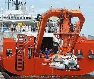
In the case of one of the DSAR series submersible with which FCL were recently involved, a fully equipped decompression facility was provided on a ‘raft’ which fitted into the deck of the mother ship but also provided the facility, if deemed necessary, to mobilise the complete system to an alternative vessel inside 24 hours.
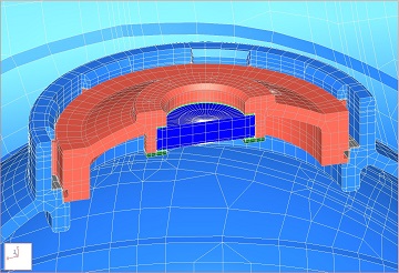
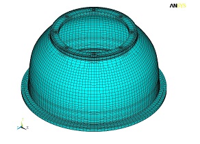
During the course of the development of the submersible design, a need was identified for supporting work to accurately establish the loading arising during transfer-under-pressure (TUP) operations between the submersible and the on-ship decompression facilities. Recognising the complexity of the raft system it was judged impractical to attempt to include representation of all items with the level of detail deemed necessary for formal design substantiation. Instead, the aim of the work was restricted to establishing limiting loads arising at the various component interfaces for subsequent application to separate, more detailed solid-element models.

Analyses were therefore performed using a shell and beam element model, developed using CREO/ Simulate finite element software. Due to the non-linear nature of many of the raft support points and the variety of load cases requiring consideration (including internal pressure, weight, ships motions induced accelerations, ship’s deck deflections and differential thermal expansion), multiple analyses were run with different constraint sets selected to best suit the anticipated behaviour under each given load condition.
Analysis ‘measures’ were used to automatically extract the internal forces arising at selected sections through the structure, and combination of the effects of the various load cases was then achieved via the development of a complex spreadsheet tool which permitted full consideration of all potential loading permutations.
The approach adopted enabled FCL to successfully complete the work within a tight timescale dictated by the overall project schedule.
The results provided a full understanding of the structural behaviour of the raft system and also produced a detailed set of design loads acting at the various interfaces, which facilitated the subsequent substantiation of the submersible and the other TUP system components, including the transfer lock and the pair of compression chambers.

Please use this form if you have any questions about our capabilities or would like to obtain a quotation.
Alternatively, you are welcome to call or contact us by e-mail.
+44 (0)1992 585450 enquiries@finglowconsultants.co.ukYour enquiry has been safely and securely received. Our office is open weekdays from 9am to 5pm - you can expect a response during the next 2-3 working hours.