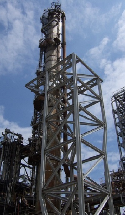
With the application of ever more stringent environmental legislation governing oil refinery emissions, the efficient separation of catalyst fines from fluid catalytic cracking unit (FCCU) flue gas streams is becoming more important than ever before.

In a modern refinery this is generally achieved by passing the flue gas through four separate stages of cyclonic separation: the first two of which are typically located within the regenerator vessel itself, the third which is located prior to the turbo-expander and the fourth which collects catalyst solids from the third stage underflow.
As a stand-alone item, the fourth stage separator must be designed as a pressure vessel, but until recently it was common practice to utilise internal refractory lining to reduce the metal temperatures arising in the pressure envelope, thereby simplifying the design task for this item. However, in order to prevent condensation issues, process licensors have recently begun to specify the use of an insulated 'hot wall' design for fourth stage separators, where the pressure envelope must be designed to withstand the full process temperatures which approach 800°C. At such temperatures, the materials of construction exhibit significant time-dependent behaviour or 'creep', necessitating the application of extremely low values of allowable stress in order to safely withstand the required operational life of the unit.
FCL were contracted to undertake the mechanical design of the very first examples of this type, destined for a refinery in Indonesia, which drew on almost all of our areas of expertise in bringing the project to a successful conclusion.
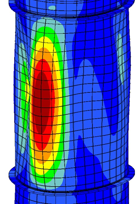
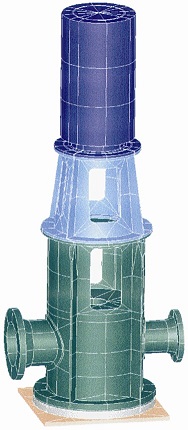
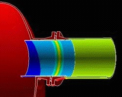
Design substantiation was carried out in accordance with ASME Section VIII Division 1, and although design-by-rule methods were used wherever possible, a number of aspects of the design necessitated the use of design-by-analysis methods based on the results of linear elastic stress and thermal analyses carried out using CREO/ Simulate and ANSYS MECHANICAL finite element software.
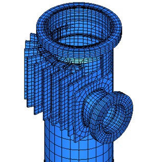
These features included the stiffened rectangular tangential inlet which was also subject to significant piping loads, and the support skirt which was subject to extremely onerous temperature gradients. In this latter area, careful optimisation of the insulation extent with a 'hot-box' at the top of the skirt, allied with the adoption of assessment methods provided in ASME Section III Division 1, was required in order to achieve a satisfactory design.
In addition to carrying out mechanical design of the unit, FCL also undertook responsibility for preparation of a complete set of fully detailed fabrication drawings, addressing not just the principal design but also the required hydrotest and transportation arrangements, thereby permitting our client to approach their selected fabricator with a fully defined task.

Please use this form if you have any questions about our capabilities or would like to obtain a quotation.
Alternatively, you are welcome to call or contact us by e-mail.
+44 (0)1992 585450 enquiries@finglowconsultants.co.ukYour enquiry has been safely and securely received. Our office is open weekdays from 9am to 5pm - you can expect a response during the next 2-3 working hours.