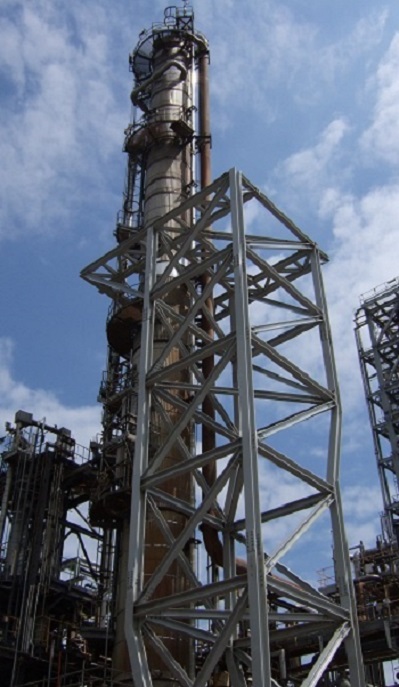
Aided by a long-standing relationship with one of the world’s leading oil refinery cyclone manufacturers, FCL have gained extensive experience in the design of such cyclone systems, together with the reactor and regenerator vessels in which they are typically located.
It is frequently the case that ageing plant or a desire to increase productivity dictates the replacement of these cyclone systems, often combined with provision of a new top dished head complete with the plenum chamber which receives the outlet flow from the cyclones.

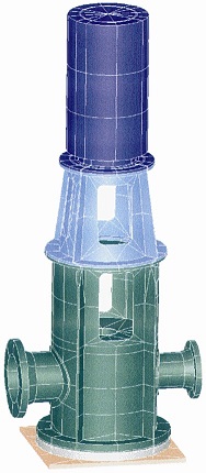
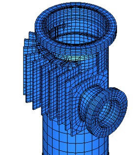
In a typical example of such work, FCL were involved in the design of a replacement top head, plenum chamber and two-stage cyclone system for a large regenerator vessel located at a refinery in Norway. Mechanical design of the vessel head was carried out using design-by-rule methods in accordance with ASME Section VIII Division 1, while design of the plenum chamber and cyclone system was carried out using a combination of design-by-rule and design-by-analysis methods.
The elevated operating temperatures to which the vessel internals are exposed (in excess of 750°C) necessitates the adoption of time-dependent design stresses for the various operating scenarios, with the combined creep damage accrued over the complete operating duty then assessed using life-fraction methods.

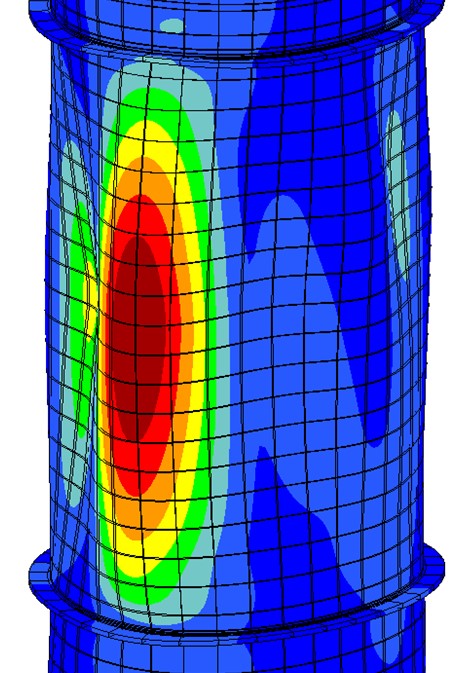
In addition to these aspects of the work, a further significant area of concern was the provision of lifting lugs on the vessel head. In order to suit the required installation procedure,
there was a need to pre-assemble the refractory-lined head and cyclones in a temporary ‘cradle’ before lifting the complete assembly, weighing around 400 tonnes, into final position. The use of a relatively thin head combined with a need to minimise distortions to prevent damage to the refractory lining made this a particularly challenging task. After preliminary calculations demonstrated that this could not be practically achieved with lugs located in ‘traditional’ fashion on the outer part of the head, FCL provided a solution by locating the lugs above the junction with the internal plenum chamber to take advantage of the additional stiffness provided by this item, using design-by-analysis methods to demonstrate the adequacy of this unconventional arrangement.
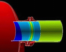
The work also included mechanical design, again largely carried out using design-by-analysis methods, of replacement air inlet nozzles located in the intermediate conical shell of the regenerator vessel and of a replacement flue gas redistributor.
FCL’s scope was completed by substantiation of the existing vessel shell sections and support skirt to confirm that sufficient margins were present in the design of these items to accommodate the increased weight of the replacement head and cyclones.

Please use this form if you have any questions about our capabilities or would like to obtain a quotation.
Alternatively, you are welcome to call or contact us by e-mail.
+44 (0)1992 585450 enquiries@finglowconsultants.co.ukYour enquiry has been safely and securely received. Our office is open weekdays from 9am to 5pm - you can expect a response during the next 2-3 working hours.